Stop Frozen Pipes Before It Happens
In cold climates, insulation alone often fails to prevent pipes from freezing. A well-designed and installed pipe freeze protection system ensures continuous water flow and prevents costly building damage.
Dependable Freeze Protection
If exposed water pipes, pumps, and other equipment have you worried in winter, King’s self-regulating electric heat trace cables are the solution. These cables prevent water in pipes, pumps, and other equipment from freezing by adjusting their power output based on the surrounding temperature. This ensures energy efficiency and prevents overheating, making them suitable for a variety of commercial and industrial buildings.
Step 1: What Size Cable (Watts/ft.) Do I Need?
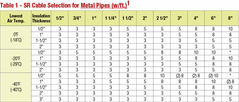
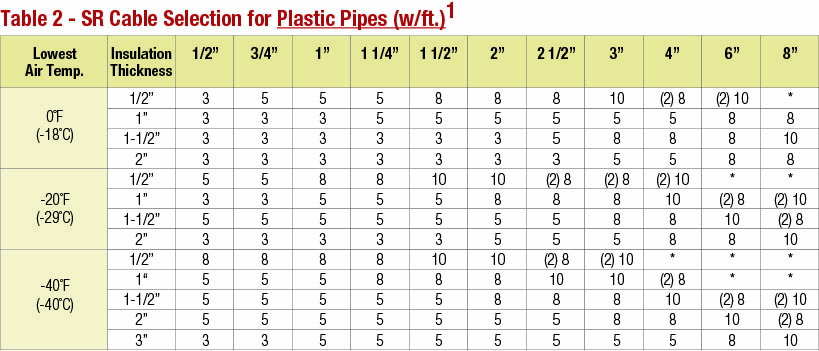
Use the below chart to determine what watts/ft cable is best suited for your application
based on Lowest Air Temp, Insulation Thickness and Pipe Size.
Heating Cable Selection for Pipe Freeze Protection
Use TABLE 1 to select the cable size for metal pipes and use TABLE 2 for plastic pipes. Read across the table to find the pipe size, then drop down to the row corresponding to the design air temperature and the thickness of the insulation that will be used. The cell that intersects will give the power (watts/ft.) of the heating cable required, it may also have a (2) in the cell which means 2 cables are required.
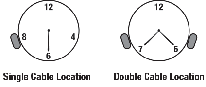
For a single cable, run it straight along the bottom of the pipe in the 4 or 8 o’clock position. If two cables are required, attach them at the 4 and 8 o’clock positions as shown in the figure above.
Step 2: How Much Cable Do I Need?
Use the below formula to estimate the length of heat cables need,
based on your pipe length, number of valves and other splices or connections.
CALCULATE THE TOTAL HEATING CABLE LENGTH
Cable length = A+B+C+D+E+F
A. Pipe length x number of cables
B. 4 ft. x number of valves
C. 2 ft. x number of flanges, supports, etc.
D. 1 ft. for each power connection
E. 2 ft. for each splice connection
F. 3 ft. for each tee connection
= Total heating cable length
MAXIMUM CIRCUIT LENGTH ALLOWED
Ensure that your circuits do not exceed the maximum circuit
length listed in TABLE 3. If necessary, use additional shorter circuits
EXAMPLE:
Pipe Size: 2” metal pipe Valves: 2
Lowest air temp: -20°F Pipe supports: 12
Insulation thickness: 1” Power connections: 1
Cable selection: (1) 5w/ft. (from table 1) Splice connections: 1
Pipe length: 80 ft.
HEATING CABLE REQUIRED
A. Pipe length x number of cables 80 ft. x 1 = 80 ft.
B. 4 ft. x number of valves 4 ft. x 2 = 8 ft.
C. 2 ft. x number of flanges, supports, etc. 2 ft. x 12 = 24 ft.
D. 1 ft. for each power connection 1 ft. x 1 = 1 ft
E. 2 ft. for each splice connection 1 ft. x 1 = 1 ft
F. 3 ft. for each tee connection 3 ft. x 0 = 0 ft
= Total heating cable length 114 ft.
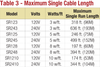
Maximum Single Cable Length: The maximum length of a single cable run is noted in TABLE 3 and cannot be exceeded. If the application requires a longer cable run, then multiple cables and additional power circuits must be used.
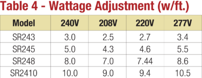
Wattage Adjustment (w/ft.): When using 240 volt SR cable on 208, 220 or 277 volt applications, the power output (wattage) must be adjusted. Refer to TABLE 4 for the adjusted watts/ft. of the cable when operated at a voltage other than 240 volt.
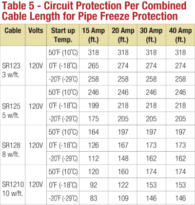
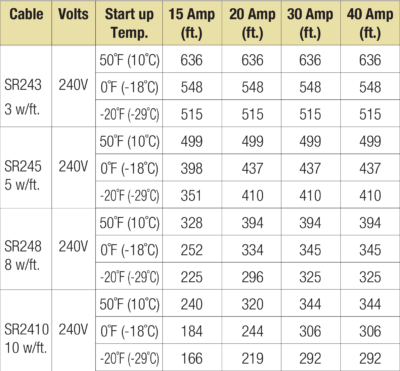
Circuit Protection Per Combined Cable Length for Pipe Freeze Protection
Circuit protection depends on the length of cable required and the start-up temperature since the cable will draw more power (wattage) when cold. Multiple cables can be run from a single power circuit up to a maximum combined length as noted in TABLE 5. Larger amperage circuit breakers can handle longer combined cable lengths, but the maximum length for
a single cable run does not change. The NEC requires the use of ground fault protection breakers for heating cable.
NOTE: 240 volt cable lengths in TABLE 5 are also good for 208, 220 and 277 volt.
