Installation Setup and User Guide
Step-By-Step Guide for Programming your Thermostat
This guide will fully explain how to move through each option on the installer menu. It is recommended to read through this guide once before installing, because the installer menu will time out after 30 seconds of inactivity.
It will help to have the ThermaLink Instructions opened to page 12 under the Installer/Technician Setup Menu.
Navigating and Setup in the Installer Menu
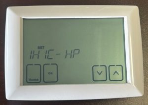
Step 1: You will first be asked to choose the System Mode and Stages.
The options are 1H1C-HP, 2H1C-HP, 2H2C-HP, 3H2C-HP, 1H1C-CS, 1H2C-CS, 2H2C-CS, and 1H0C.
If you chose 1H1C, your next question will ask if you want 1 Fan Speed or 3 Fan Speeds. If you did not select 1H1C, proceed to the next step. Verify if your unit is capable of 3 fan speeds to use the 3 Fan Speed setting. This will replace your Y2 and W2 with your medium and high fan speed. That is why it is only available for 1H1C systems. Check in the instructions under Fan Speeds to learn more about wiring and functionality of the 3 Fan Speeds.
If you chose 2H1C-HP or 3H2C-HP, your next question will be Set: Heat 2 or Set: Heat3 respectively. If you did not select 2H1C-HP or 3H2C-HP, proceed to the next step. This is asking if you want to have your second stage of heat (2H1C) or third stage of heat (3H2C) to be 24V Controlled via terminal W2 or line voltage controlled via the KRFLR-120/240V relay.
Note: If you choose to use your KRFLR-120/240V Line Voltage relay as the 2nd or 3rd Stage of heat, you will no longer have the ability to use Backup/Emergency Heat. This is because it will already be turned on whenever the system calls for Emergency Heat.
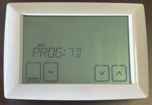
Step 2: It will ask you if you want 7D, 5/2, or 5/1/1 Programmable settings. This will alter your User Menu for the heating and cooling schedule, which is the the Wake/Leave/Return/Sleep Temperatures and Times for various days of the week. If you want to program every single day individually, use 7D. If you want to program just the weekday and the weekend, select 52. If you want to program the weekday, Saturday, and Sunday, select 51. Reference page 14 and 15 in the instructions for a full breakdown.
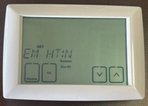
Step 3: It will ask EM HT: N/Y. By default, this is turned Off (N). Setting this to Y will turn on the Emergency Heat System Mode in the Main Menu.
Note: You DO NOT need to turn this on to have your Emergency/Boost Electric Heat turn on. This is a separate mode where your Line Voltage Emergency Heat (Electric Resistance Heater) will automatically turn on in the Second Stage with no delay.
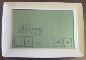
Step 4: It will ask AUTO:N/Y. By default, this is turned Off (N). Setting this to Y will allow you to select the Auto Changeover system setting in the Main Menu. This will allow the thermostat to automatically change between heating and cooling modes. Applications with a Heatpump will likely want to use this setting.
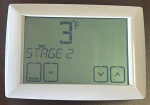
Step 5: It will ask STAGE 2: 3°F. This is asking what you want your 2nd Stage Offset to be, or how much differential do you want from the Set Point Temperature before your 2nd Stage Heating or Cooling kicks on. This will also determine when your Emergency Heat can turn on, because it will only turn on in the 2nd Stage. By default, this is 3°F, but you can choose between 2°F to 5°F. If you chose your 1st stage differential to be 2°F instead of 1°F (Default), you will only be allowed to select between 3°F to 5°F.
NOTE: If you are using AUTO mode, this differential will be in addition to the Deadband zone. Therefore, using the default Deadband zone, a 3°F 2nd Stage Offset will mean your 2nd stage won’t turn on until a 5°F differential from the setpoint.
Next, if you chose 3H2C-HP, it will ask you your 3rd Stage Offset. If you did not select 3H2C-HP, move to the next step. Your 3rd Stage of heat can come on 1°F, 2°F or 3°F above your 2nd Stage Offset. For example, if you selected 3°F for 2nd stage offset, you can select between 4°F, 5°F, or 6°F. Additionally, the same note above applies here. Your total offset will increase based on the deadband in AUTO mode only.
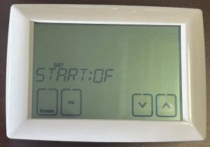
Step 6: It will ask Start:OF or Start: ON. This is asking if you want to use optimal start when reaching your setpoints for Wake/Return temperatures. This means that your room temperature would be at the setpoint at the exact time it is planned for instead of just starting to reach the setpoint at that time. This is if you would like to wake up to the planned temperature instead of waking up to a unit working to get to the set temperature.
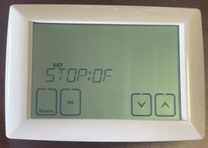
Step 7: It will ask Stop:OF or Stop:ON. This is the same as above, but for Leave/Sleep temperature setpoints. It will attempt to reach the future Leave/Sleep setpoint right at the planned time instead of waiting to adjust the temperature until the planned time.
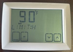
Step 8: It will ask for LIMIT:H. This is your maximum heat setpoint. Default is 90F. Use this feature to reduce the max temperature a user can set a unit to.
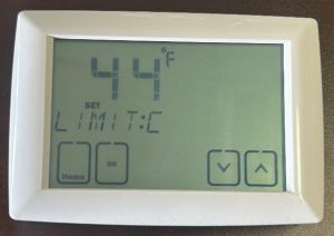
Step 9: It will ask for LIMIT:C. This is your minimum cooling setpoint. Default is 44F. Use this feature to increase the minimum temperature a user can set a unit to.
The next questions will be specific for the additional accessories that can be ordered with the KRF-Kit. These include the Motion Sensor, Window/Door Sensor, Master Switch, and Outdoor Sensor. If you do not have any of these pieces, you can leave all of these next options to their default N (Off) value.
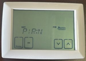
Step 10: It will ask PIR: N/Y. This is by default turned off. If you have a PIR Sensor, set this to Y. If you select Y, it will follow up asking how long you would like to wait with no motion detected before setting the temperature of the room back. You can select between 10 minutes, 30 minutes, or 60 minutes. Make sure your sensor is paired. The pair button is on the back of the sensor. Follow the pairing instructions on the main installation instructions to pair the PIR sensor to the thermostat.
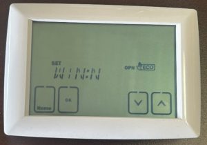
Step 11: It will ask WIN: N/Y. If you have a window sensor installed, set this to Y (On). Make sure your Window Sensor is paired. The pairing button is inside the larger portion of the sensor, so a small screwdriver is needed to remove the back cover to find the pairing button. Follow the pairing instructions on the installation instructions to pair the sensor to the thermostat.
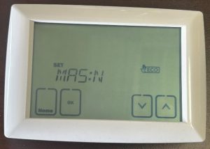
Step 12: It will ask MASTER: N/Y. If you have a Master Setback switch, set this to Y (On). Make sure you sensor is paired to the thermostat. Use the RF Pair button on the Master Switch to connect it with the thermostat. Follow the pairing instructions on the installation instructions to pair the sensor.
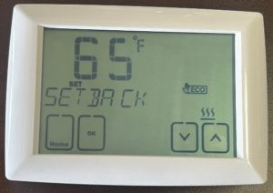
Step 13: It will ask you Setback with the Heat Symbol and the default temperature 65F flashing. This is your setback for heating. If one of your sensors activates, this is the temperature your heat will attempt to maintain in heating mode. In auto mode, it will use this temperature and the next temperature to set 2 limits, one for heating and one for cooling.
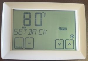
Step 14: It will ask you Setback with the Cooling Symbol and the default temperature 90F flashing. This is your setback for cooling. If one of your sensors activate, this is the temperature your cooling will maintain within the room, i.e. your cooling won’t turn on unless the room temperature exceeds 90F. In AUTO mode, this is the top limit of the control temperature. By default in AUTO mode, your thermostat will maintain a room temperature between 65F and 90F, so your HVAC system will not turn on unless you fall below 65F or exceed 90F.
Step 15: It will ask you ODSEN: N/Y. If you have an outdoor temperature sensor, set this to Y (On). This accessory will also need to be paired to the thermostat. Follow the pairing guide in the installation instructions. This sensor works differently than the others, as it does not use a setback temperature. The Outdoor Sensor tracks the outdoor temperature. Using this sensor will determine when your Electric Resistance Heat or Emergency Heat will activate.
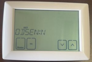
If you selected ODSEN: Y, the next screen will ask you to select a ODSEN temperature. Default is 32F. This is the outdoor temperature that is required for you to turn on your Electric Resistance Emergency Heat. If the outdoor temperature is less than this setpoint and you are in Stage 2 differential, your emergency heat will immediately turn on. The ODSEN temperature can be set between 0F and 45F. It should be decided by the installer what outdoor temperature your Heatpump or HVAC system becomes less efficient than electric heat or what temperature it will need help to maintain comfortable indoor temperatures.
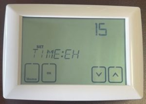
Step 16: If you do not have an outdoor sensor, it will ask you Time:EH. This is the amount of time the thermostat will wait before activating your Emergency Electric Resistance Boost Heat. If you cannot reach the setpoint within 5-30 minutes and your differential is greater or equal to your 2nd stage differential, your Emergency Heat will turn on. Default time is 15 minutes.
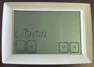
Step 17: It will ask LIGHT: N/Y. This is if you want to leave the backlight permanently on. This is only recommended for 24V wired power to the thermostat. Using this with primary battery power will drastically reduce your battery lifetime.
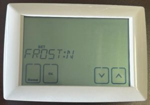
Step 18: It will ask you FROST: N/Y. This is your Frost Protection setting. If you turn this on, while in OFF system mode, your thermostat will call for heat if it drops below 40F room temperature. This temperature set point is not adjustable.
Related Articles
Can’t find your answer in our support center? Contact us directly.