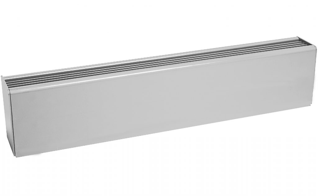
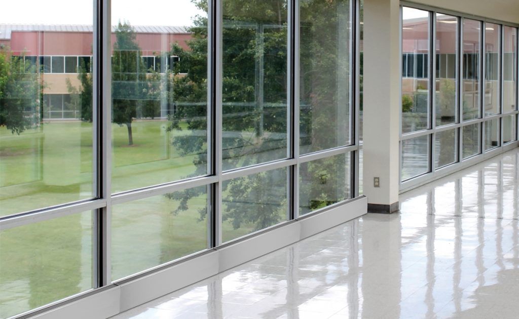
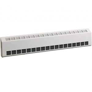
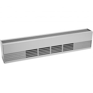
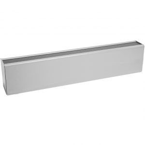
This draft heater is used for tall glass walls or complete heating of large commercial spaces. The sleek lines complement any commercial building. Feed-through wire-ways help provide continuous wall-to-wall warmth. Controls can be conveniently mounted in either end of the heater or in a separate section. Heated sections can be anywhere within the case. End caps are required on stand alone installation. Custom paint colors are available. Optional anodized finishes can match window finishes. Suitable for industrial and commercial uses.

- Full Length Safety Cutout
- 12 Gauge Front and Back
- Two Piece All Aluminum Construction
- Natural Convection Heat
- Silent Running
- Extended Backs & Fronts Available
- 4” Junction-Boxes At Both Ends
- ¾” EMT Raceway Standard
- 7” H x 5” D Cabinet Size
- Available in Gray, Almond, Bronze, White, & Semi-Gloss Black Finishes
- Proudly Made in the USA with U.S. & Global Materials
- 1-Year Warranty
Protection From Low Insulated Glass Windows
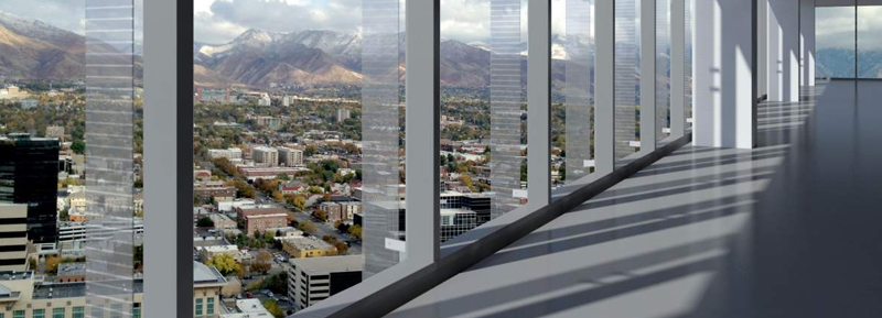
Used for tall glass walls or complete heating of large commercial spaces. The sleek lines compliment any commercial building.
Now That’s Smart!
Available Models
Ordering Information
| STANDARD MODEL | UPC | FRONT INTAKE MODEL | UPC | VOLTS* | WATTS | LENGTH | NOMINAL WATTS / FT. |
|---|---|---|---|---|---|---|---|
| LB22403 | 14300 | LBF22403 | 14364 | 240 | 376 | 2' | 188 |
| LB22405 | 14302 | LBF22405 | 14366 | 240 | 500 | 2' | 250 |
| LB22407 | 14304 | LBF22407 | 14368 | 240 | 750 | 2' | 350 |
| LB22410 | 14306 | LBF22410 | 14370 | 240 | 1000 | 2' | 500 |
| LB32405 | 14308 | LBF32405 | 14372 | 240 | 564 | 3' | 188 |
| LB32407 | 14310 | LBF32407 | 14374 | 240 | 750 | 3' | 250 |
| LB32411 | 14312 | LBF32411 | 14376 | 240 | 1125 | 3' | 350 |
| LB32415 | 14314 | LBF32415 | 14378 | 240 | 1500 | 3' | 500 |
| LB42407 | 14316 | LBF42407 | 14380 | 240 | 750 | 4' | 188 |
| LB42410 | 14318 | LBF42410 | 14382 | 240 | 1000 | 4' | 250 |
| LB42415 | 14320 | LBF42415 | 14384 | 240 | 1500 | 4' | 350 |
| LB42420 | 14322 | LBF42420 | 14386 | 240 | 2000 | 4' | 500 |
| LB52409 | 14324 | LBF52409 | 14388 | 240 | 940 | 5' | 188 |
| LB52412 | 14326 | LBF52412 | 14390 | 240 | 1250 | 5' | 250 |
| LB52418 | 14328 | LBF52418 | 14392 | 240 | 1875 | 5' | 350 |
| LB52425 | 14330 | LBF52425 | 14394 | 240 | 2500 | 5' | 500 |
| LB62411 | 14332 | LBF62411 | 14396 | 240 | 1125 | 6' | 188 |
| LB62415 | 14334 | LBF62415 | 14398 | 240 | 1500 | 6' | 250 |
| LB62422 | 14336 | LBF62422 | 14400 | 240 | 2250 | 6' | 350 |
| LB62430 | 14338 | LBF62430 | 14402 | 240 | 3000 | 6' | 500 |
| LB82415 | 14340 | LBF82415 | 14404 | 240 | 1500 | 8' | 188 |
| LB82420 | 14342 | LBF82420 | 14406 | 240 | 2000 | 8' | 250 |
| LB82430 | 14344 | LBF82430 | 14408 | 240 | 3000 | 8' | 350 |
| LB82440 | 14346 | LBF82440 | 14410 | 240 | 4000 | 8' | 500 |
| LB92416 | 14348 | LBF92416 | 14412 | 240 | 1692 | 9' | 188 |
| LB92422 | 14350 | LBF92422 | 14414 | 240 | 2250 | 9' | 250 |
| LB92433 | 14352 | LBF92433 | 14416 | 240 | 3375 | 9' | 350 |
| LB92445 | 14354 | LBF92445 | 14418 | 240 | 4500 | 9' | 500 |
| LB102418 | 14356 | LBF102418 | 14420 | 240 | 1875 | 10' | 188 |
| LB102425 | 14358 | LBF102425 | 14422 | 240 | 2500 | 10' | 250 |
| LB102437 | 14360 | LBF102437 | 14424 | 240 | 3750 | 10' | 350 |
| LB102450 | 14362 | LBF102450 | 14426 | 240 | 5000 | 10' | 500 |
Ordering Information - Accessories
| MODEL | DESCRIPTION |
|---|---|
| LB-100BS | 1FT. Blank Section |
| LB-200BS | 2FT. Blank Section |
| LB-300BS | 3FT. Blank Section |
| LB-400BS | 4FT. Blank Section |
| LB-500BS | 5FT. Blank Section |
| LB-600BS | 6FT. Blank Section |
| LB-700BS | 7FT. Blank Section |
| LB-800BS | 8FT. Blank Section |
| LB-900BS | 9FT. Blank Section |
| LB1000BS | 10FT. Blank Section |
Ordering Information - Options
| MODEL | DESCRIPTION |
|---|---|
| LB-IC | Inside Corner |
| LB-OC | Outside Corner |
| LB-EC | REQUIRED End Cap (Specify right or left) 1/2" |
| LB-SP | Splice Plate |
| LB-WT | Wall Trim |
| LB-MESH | 1/4" Wire mesh under discharge grill |
| LB-PD-FM | Pedestals (field mounting) |
Ordering Information - Control Sections
| MODEL | DESCRIPTION |
|---|---|
| LBCS-R | Relay Section - SPST, 20 Amp, 277 Volt |
| LBCS-RDS | Relay, Disconnect Switch Section, 20 Amp |
| LBCS-TR | Xformer Relay Section - SPST, 25 Amp, 277 V, 24V Control |
| LBCS-TRDS | Transformer Relay, Disconnect Switch Section, 20 Amp |
| LBCS-PE | PE Relay, SPST, 20 Amp |
| LBCS-DS-FUSED | Disconnect Switch, with 20 Amp fuse and fuse block |
Ordering Information - Integral Controls
| MODEL | DESCRIPTION |
|---|---|
| ITS | Integral Stat 25 Amp, SPST-120-277 Volts - STD-LF or RT |
| ITD | Integral Stat 20 Amp, DPST-208-240 Volts - STD-LF or RT |
| IDS | Integral Disconnect Switch 20 Amp, 120-277 V - STD-RT side |
| LBCS-TS | Thermostat Section - SPST, 20 Amp, 277 Volts |
| LBCS-TSDS | Thermostat Disconnect Switch Section, 20 Amp |
| LBCS-TSR | Thermostat Relay Switch, 20 Amp |
| LBCS-TSDSR | Thermostat Disconnect Switch, Relay Section, 20 Amp |
| LBCS-DS | Disconnect Switch, Section, 20 Amp |
Engineering Specs
• Model LB Architectural Draft Barriers shall be 7″ H and 5″ D. The front cover shall be 12 gauge extruded aluminum construction suitable for architectural, commercial and industrial use with 1⁄4″ pencil-proof intake and discharge grilles. The one-piece cover shall be extruded for maximum strength and available in lengths up to 12 feet.
• The cover shall be linear mount to the 12 gauge heater back with no visible fasteners. The 12 gauge heater back shall be suitable for mullion-to-mullion mounting.
• Standard painted finishes or optional anodizing shall be provided as specified by the architect. Color matching to architect’s specifications are available as optional finishes.
• Heat sections from 2 -10 feet are available. All heaters shall contain 3⁄4″ EMT built-in raceway with factory wiring to provide field wiring from either end when optional controls are not included.
• 1⁄2″ and 3⁄4″ knockouts shall be provided in the side and rear of the heater junction-box to permit end-to-end wiring. All blank sections shall be fully enclosed to allow branch circuit wiring.
• All heaters shall contain a full length thermal overheat protector with automatic reset. Wattages shall be available from 100 to 500 Watts per foot. Heating elements shall be tubular stainless steel or aluminum tubing with aluminum fins mechanically bonded to ensure efficient heat transfer.
• Element fin temperature shall not exceed 350°F to ensure long element life. Elements shall be center anchored and free-floating in nylon bushings at each end.
• Control sections are 6″ or 12″ for pneumatic relay, transformer relay, fused disconnect or duplex receptacle. Optional built-in heater controls shall include thermostats (single and double pole) and disconnect switches.
• Built-in controls shall be tamper-proof and shall be adjustable with a blade screwdriver through the discharge louver.
• All heaters are Underwriters Laboratories listed.
• Tested under UL Safety Standard UL#1042.


